


Abstract:
Anti lock brakes are a safety system on motor vehicles which prevent the wheels from locking in panic braking situations. Braking systems that have the capability of releasing pad pressure as function of independent wheel velocity, allows the driver to maintain steering control under heavy braking, by preventing a skid, and allowing the wheels to rotate which maximizes lateral control. The driver maintains full control as the vehicle comes to a stop. Anti-lock brakes have been a common commodity in production vehicles since the 1980’s. Their ability to reduce stopping distances in precarious or panic situations has made them a standard safety device on all motor vehicles. Trailing vehicles have yet to adapt such a standard. This project will incorporate a trailer brake controller that has wheel velocity feedback and rudimentary adaptive control for various real world situations. The project aims to create a standalone controller that has the ability to generate proportional braking while, considering the wheel velocity. Using an 8 bit microcontroller I will attempt to create a sufficient controller that manages a variety of real world road conditions. The system is a multiple input single output system which belongs to a class called MISO systems. The state of the system will determine the output while the feedback loop will provide necessary data to allow compensation for the particular case when the wheels lock up. This will allow the system user (the driver) to maintain stability while braking.
Introduction:
The anti lock brake problem presents many challenging issues from the design aspect. To design a controller that has the ability to manage proportional braking while simultaneously monitoring wheel frequency and adjust output as the feedback information is gathered is not a trivial task.
Using an array of mechanical and electronic devices I will create a control system to manage braking pressure. The system at the most fundamental level will consist of two sensors and one actuator. The primary input sensor for the controller is the analog devices ADLX320 dual axis accelerometer. I will be using the ADLX320EB evaluation board for its convenient 5 pin header. The accelerometer will provide direct acceleration data in the direction of braking as well as lateral accelerations experienced by the vehicle. This project will focus on a single direction; the deceleration direction of the vehicle with provisions to incorporate a dual axis input which will ultimately provide for a much more dynamic adaptive control system in the future. Since the trailer is mounted to the vehicle with rigid mounts, (generally speaking) the deceleration experienced by the trailer will be equivalent to that of the vehicle. This allows me to put the brake controller in the cab of the vehicle so that the user can interface with the controller real time as he or she wishes. This will allow the user to adjust the controller for various loads. Advancement to this project could contain various strain gauges under the platform of the trailer to assess the changing loads and provide data as an additional input to the MCU for further adaptive control. This would eliminate the user altogether and would allow controller to be mounted on the trailer directly. For this project I will be interfacing with MATLAB to adjust these values within the microcontroller. In practice, a rotary encoder would perform this task with the MCU directly.
The second sensor is a Cherry GS100701 Hall Effect proximity sensor. This is a magnetically biased proximity sensor that provides a digital signal, toggling from high to low in the presence of a ferrous material. I fabricated a prototype encoder with an acrylic disc which I machined to accommodate half inch steel plugs, spaced evenly every 18 degrees. The brains of the operation will be computed using the Atmel ATmega16, 8 bit AVR microcontroller using RISC architecture. The actuator is an electromagnetic coil that is magnetized as the coil is charged. The coil is then attracted to the spinning drum, like a magnet on a fridge. As the drum spins a mechanical mechanism is used to translate the drag from the electromagnetic force into a linear mechanical force which then creates pressure on the brake shoes. The friction between the brake shoes and the brake drum provides the mechanism to slow the wheel velocity on the trailer.
This report will show many of the considerations and many of the particular details that were encountered during the design of this system. The above description of the project is a macroscopic view of the system but does not account for many of the real world variations that a vehicle may encounter. Much of the software is tailored to deal with these situations. The Methods section will give insight into the dirty details that make this project come alive.
Methods:
Sensors
The sensors are the most integral part of any control system. Without correct, properly mounted sensors, the system will have no way of accurately processing the precise state of the system. With that consideration I made the decision to use an accelerometer to measure the deceleration of the vehicle. The alternate idea was to use an adapter between the vehicle and trailer with a durable composite compound, which would flex slightly and could measured with strain gauges. The measurement could be translated into applicable data with respect to the vehicles deceleration. For example, if the trailer is experiencing acceleration, the material would be under tensional forces and would stretch, under braking (deceleration), the material would be under compression and would compress. The strain gauges would measure the deflection and provide relative information about the forces on the trailer. I opted out of that idea because the strain gauge system would need to have an added adapter between the vehicle and trailer. This added mechanical device could possibly eliminate the need for a feedback sensor, but would add a longer wheel base and would respond to resonance modes if the vehicle’s suspension oscillates. With the added liability of possible mechanical failure, I confidently decided to implement the accelerometer design.
Since the mounting device connecting the vehicle to the trailer is rigid, the accelerometer could be placed in the controller box which is mounted inside the cab so the user would be able to interact with it on the fly. The rigid mount is essential because if the vehicle experiences a deceleration, the trailer must experience the same deceleration. I decided that it would be advantageous to know if the vehicle is accelerating or decelerating. To do this I designed a circuit (Figure 1) using two op amps and various resistors, I set a virtual ground at 2.5 volts which corresponds to a nominal acceleration of 0 g’s.
Figure 1
The accelerometer can sense forces up to 5 g’s, however in a vehicle braking situation I expect no more than 2 g’s of deceleration. Therefore I conditioned (amplified) the signal from the accelerometer with the second op amp to saturate at 5 volts which correspond to the maximum expected g-force of 2 g’s. This way I could maximize resolution for my expected forces. Table 1 shows the mapping from acceleration to voltage.
G's (Force) |
Vout |
-2 |
0 |
-1 |
1.25 |
0 |
2.5 |
1 |
3.75 |
2 |
5 |
Table 1
The feedback sensor was chosen for it’s rugged applications. The Hall Effect proximately sensor is impervious to many elements and operates in very harsh conditions. The sensor is only affected my local magnetic fields. Dirt and debris must be considered near the brake environment. This particular sensor is universally used in the automotive industry. It is usually mounted in the differential housing; it reacts to the gear teeth on the ring gear in the rear end housing. In the presence of a ferrous object the sensor provides a clean digital pulse; high in the absence of metal and low in the presence of metal. I used the same principle, however, on trailers the wheels are spun on a free floating spindle, hence, there is no ring gear. For prototyping purposes I designed an encoder to manage this portion of the system.
Encoder
The encoder was fabricated from a 10 inch acrylic disc. I used a mill with a rotary index wheel to precisely drill counter sink holes in the material. I then used a high grade 5 ton epoxy to secure half inch round metal plugs in the disc. See Figure 2. The plugs were spaced every 18 degrees, this gives me a resolution of approximately 4.5 linear inches of vehicle travel between each reading. That means that I will have to wait a minimum distance of 5-6 inches before I will be able to determine if the wheel velocity has experience some sort of discontinuity. This resolution can be changed in practice to increase performance of the feedback system.
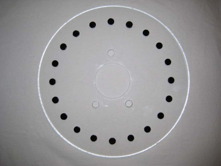
Figure 2
Microcontroller
The microcontroller is a very powerful device, yet it is limited to the integrity of the data it must process. Therefore, the incoming data must be accurate relative to the parameters that you wish to observe. I used the ATmega16 because of its versatility and its variety of onboard peripherals. I used an 8MHz crystal oscillator for an external clock. The onboard 1Mhz clock was not sufficient for the calculation load of the controller. I also utilized various timer interrupts for the encoder inputs as well as the 10 bit analog to digital converter (ADC)for the accelerometer. To actuate the system I utilized the onboard pulse width modulator (PWM). I also used the Universal Synchronous and Asynchronous Receiver and Transmitter (USART) peripheral to communicate with the PC terminal for data acquisition and MATLAB tuning or analysis. The details of the operation will be comprehensively covered in the software section.
Actuator
The actuator for the brake system is a hybrid of mechanical and electromagnetic components. The active component is the 3mH electromagnetic coil that generates a magnetic field as the coil is charged. Hence the strength of the field is proportional to the amount of charge. The coil can then be controlled using a microcontroller and some discrete components to source the current. The passive actuation is executed as the mechanical levers attached to the coil are forced in different directions, ultimately expanding the brake shoes, which applies pressure to the drum. The amount of force is directly but non-linearly proportional to the charge applied with the coil. The i-v characteristics of the coil were found empirically and are shown in Figure3. The overall impedance of the coil was found to be 4 ohms.
Figure 3
The actual mechanism is not so trivial or linear. For actuation to occur the wheel/drum must be spinning. As the drum spins the coil sits flush with the interior face of the drum. If the coil is charged the magnetic field is induced and the coil acts as a magnet as it is attracted to the face of the drum. The friction between the coil and the spinning drum provides the force needed using the kinetic energy of the spinning wheel to engage the braking mechanism.
Software
I will be using the Codevision v2 C compiler for programming the microcontroller. The Codevision compiler is very efficient for the AVR microcontroller. It also has a decent IDE with an integrated terminal for serial communication with the controller. I will also use MATLAB .m files to write quick scripts and simple GUI’s for adjusting or tuning the controllers in the future.
Implementation/Results:
This brakes system is relatively simple concept yet the implementation is far more complex. I needed a platform to test my idea and see if my design would work. To do so I designed a proto type platform on paper to test this concept, see Figure 4.
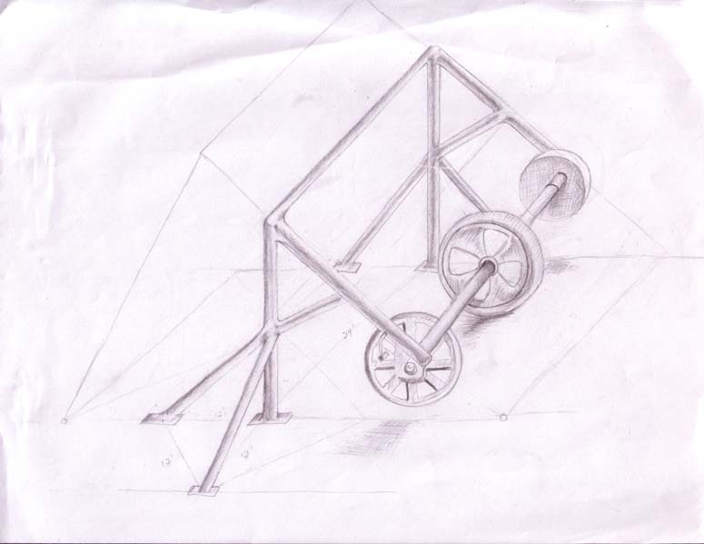
Figure 4
The inspiration for the design was to fabricate a system where all of the components are separate to ensure that all of the subsystems: actuation, feedback and load bearing, would work independently. With this system I could run a treadmill under the tire, simulating a moving ground and observe all of my data in a stationary manner. With this idea in my head I forged forward with a slightly more realistic design platform that could be attached to a trailer hitch for the inevitable road testing. The final jig is composed of 2 pieces, a stand and a swing arm which is mounted to the spindle where the wheel spins freely. The encoder was mounted on the front side of the wheel using couplers and threaded steel. The system is shown in Figure 5.
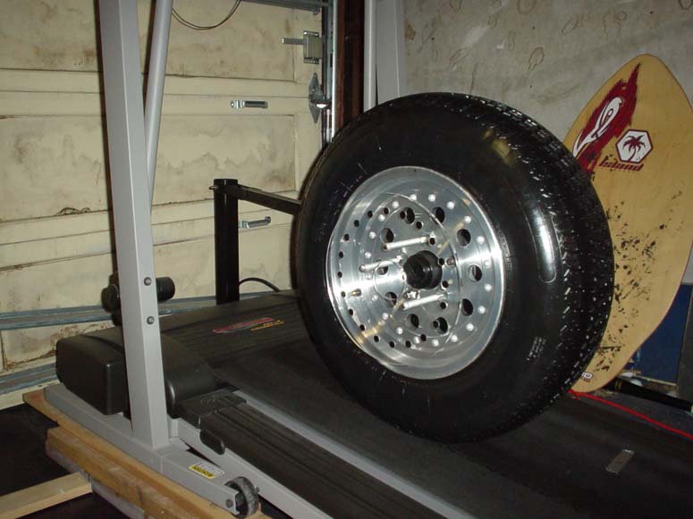 |
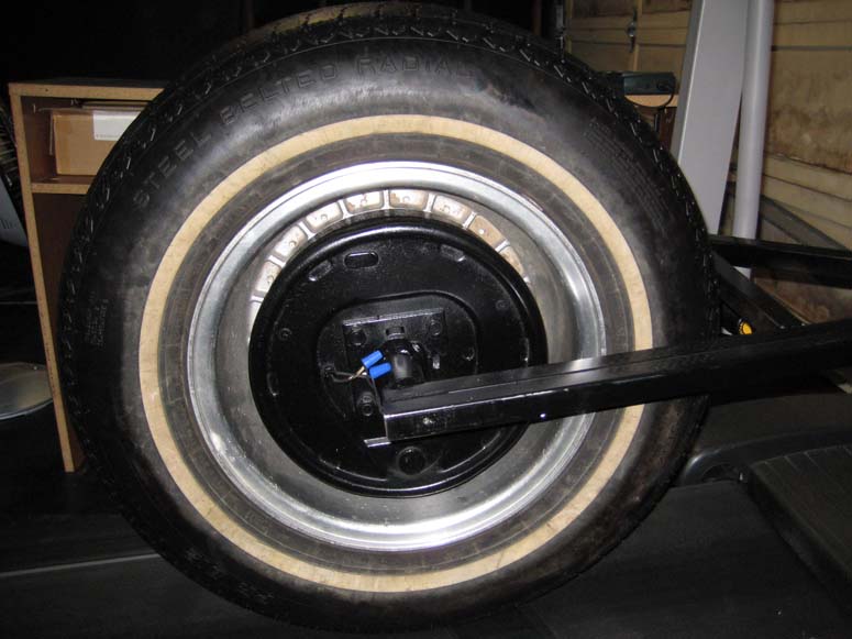 |
Figure 5
With this jig set my next task was to mount the Hall Effect sensor for the feedback loop. I didn’t necessarily need precision for mounting the sensor because I could adjust the acrylic plate or the sensor in or out to compensate. However, I quickly learned that the sensor needs absolute stability. My first attempt to mount the sensor was a major failure. I used reinforce aluminum flat stock over the tire and back down to the prospected sensor position. This was esthetically pleasing but when I turned the treadmill on, it introduced vibrations, causing the sensor to oscillate forward and backward. This resonance would have given erroneous readings as it would have induced a perceived relative motion and the microcontroller would not be able to resolve the true period between the encoders metallic plugs. This was a problem. I decided to make the sensor mounting hardware with steel to ensure vibrations were contained to a minimum. See Figure 6.
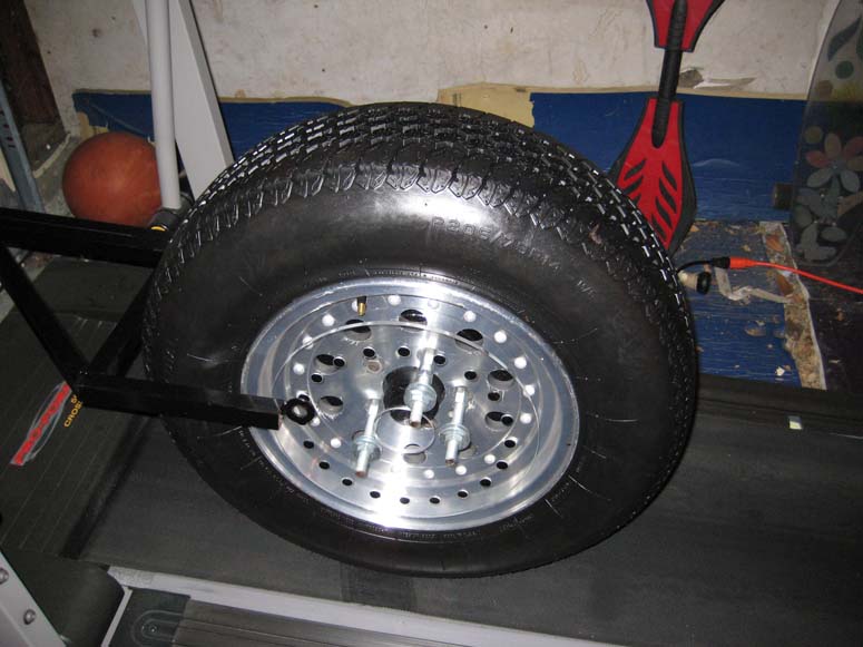
Figure 6
With a functional mechanical system intact, it was now time to attack the software to implement the sensors and actuation on the microcontroller.
After countless hours laboring over the AVR datasheets, its programmer and IDE integration with Kanda’s STK300 and STK200 development boards, I painstakingly found my way to a very powerful tool. I choose the ATMEGA16 for this particular project because of its wide variety of timers and timer applications as well as it pin out flexibility. I programmed the MCU in C, utilizing many of its peripherals. Namely the A/D and the various timer functions: PWM, output compare, and input capture. I choose to use timer one because of its 16 bit resolution. I use this timer register for the PWM as well as the input capture feature.
The first MCU peripheral I wanted to get working was the analog to digital converter. With the 10 bit A/D I have 1024 points of resolution from the accelerometer input. This voltage is directly proportional to how quickly the vehicle is stopping. Therefore I have a direct indication of the relative force I need to apply to the brakes as a function of the vehicle current braking state. The circuit responsible for conditioning the signal is shown in Figure 1. The output of the second amplifier is connected to PINA1. I also have a potentiometer voltage divider connected to PINA0 for my development platform. This way I could simulate stopping situations in a stationary position while I observe the system.
With the inputs from the accelerometer being converted into digital integers, I wanted to see the values being converted real time. To do so I set up the USART to transmit data asynchronously at 9400 Baud to the terminal in Codevision. This terminal is very useful because you can record the data flowing through the terminal to a standard text file. This is useful to analyze or even data mine if necessary. To do so you would just need to write a simple C++ program or Python script to open the text file, with the notepad file at your fingertips you could run serious data analyzing techniques depending on the scope of your project. This was a wonderful development tool and worthwhile to develop. But I still felt like something was missing. I wanted to see the values graphically real time, just like an oscilloscope. To do so I just wrote an inefficient quick and dirty Matlab GUI that takes in formatted values through the serial port that are of the form [x;y] and used the eval function to evaluate the array. The user interface can pause the scope value for inspection. Figure 7 shows a screen capture of the Accelerometer Scope GUI in the paused state. The blue plot is the sensors value or relative acceleration and the green plot is the derivative or jerk value. The corresponding C code for the MCU and the MATLAB code for the terminal GUI are located in the code section of the located at the end of report.
Figure 7
Next I wanted to get the actuation control underway for testing. The PWM on timer 1 controls the actuator via a Darlington transistor. The coil is connected to the 12V car battery and the collector of the transistor. I also implemented a flyback diode across the coil to ensure the transistor doesn’t burn up when it is turned off rapidly. See Figure 8 . When the PWM duty cycle register (OC1A) is 0, the transistor is off and no current flows through the coil. As the duty cycle increases, the transistor stays on for longer time periods allowing more current to flow through the coil. Therefore I can control the duty cycle register and directly impact proportional braking.
Figure 8
With the actuation software running I began to work with the input capture register (ICP1). I used this register with interrupts to ensure that I receive the current value of the encoder. The algorithm was relatively simple, I just test if the ICP1 register is high and record that value to the rising edge variable, or else I set the ICP1 register to a falling edge variable. I then mask or unmask the seventh bit of the TCCR1B to trigger the interrupt on the next rising or falling edge. Finally I compute the previous time period at the end of each period. I use an overflow counter to test is the vehicle is moving too slow. If the overflow counter interrupt is reached the vehicle is assumed to be stopped.
Finally, I created a pseudo controller for my stationary system. This controller accepts scaling values from the terminal or my MATLAB GUI terminal. The two scaling values that can be adjusted or tuned from the terminal is the percentage of time that the controller allows before determining if the brakes are locked up and a scaling factor for the magnitude of the proportional actuation. These values are arbitrary and would be change for various loads on the trailer. The entire design schematic is shown in Figure 9.
Figure 9
Conclusion:
This project was my first complete electrical engineering project from design to implementation. I had been thinking about the problem for many years, but I was unable to solve the problem without my education. I was able to implement the knowledge attained in my last 5 years of school to solve a complex real world problem. Various components of my design are very prototypical and scaled down to school project scale. This caused unforeseen issues in the mechanical implementation. The MCU and corresponding components interact correctly to control the proportional braking force. However the mechanical brake mechanism has inherent stiction associated with its non-linear internal operation. This issue is obvious when the controller reaches a sufficient PWM duty cycle to lock up the brakes. Once the brakes are locked, the shoes remain stuck to the drum keeping the system locked up. This is because of stiction within the brake mechanism. In the real world the weight of the trailer would break that stiction immediately and the tire would release. That caused me to abort the feedback control, because the mechanical jig I created for the project is not realistic. I have all of my components working together from the electrical side, I just need a full sized trailer to develop the actual controller.
The jig gave me confirmation that my concept could surely be put into practice so I believe this was a successful project. Phase 2 is to do some research and development with my accelerometer scope to test maximum decelerations for standard sized trucks which will help quantize the range for the real controller algorithm. I believe that moving forward with a controller for this system is not an efficient use of recourses because the proto mechanical system is just not realistic enough to warrant further development. I did however write C code for the MCU to implement the controller with the feedback elements, I just need a full scale trailer to manipulate and tune a professional level algorithm. See the code section for the commented source code.
Future Plans:
This summer I hope to develop my system on a full scale trailer. I will also be omitting the encoder plate and mounting the feedback sensor on the back side, where it will be excited by the evenly spaced cooling fins on the brake drum. This is far more realistic than having an encoder plate on the outside of the wheel.
Code:
| MATLAB (Terminal) code corresponds to Figure 7 | This is a first draft. It receives data via the serial port, which is preformatted by the MCU (See C code) and can be recognized with the eval([a;b]]) function in MATLAB. The second iteration was far more efficient as it just received 2 consecutive bytes and used Big-Endean formatting which corresponds to a 16 bit number. "Live and learn" right? |
| C (Microcontroller) Code corresponds to Figure 7 | This code is really dirty, especially without an IDE to color coordinate the text. There is some exponential smoothing that is commented out. I was playing with digital filters at the same time I was developing this software. But if you know C really well you should be able to follow it. I haven't had time to polish it all for the laymen reader. Sorry |
Pictures:
To see pictures of the project click here